Networking and communications
individual assignment:
design, build, and connect wired or wireless node(s) with network or bus addresses
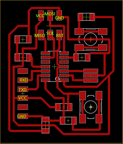
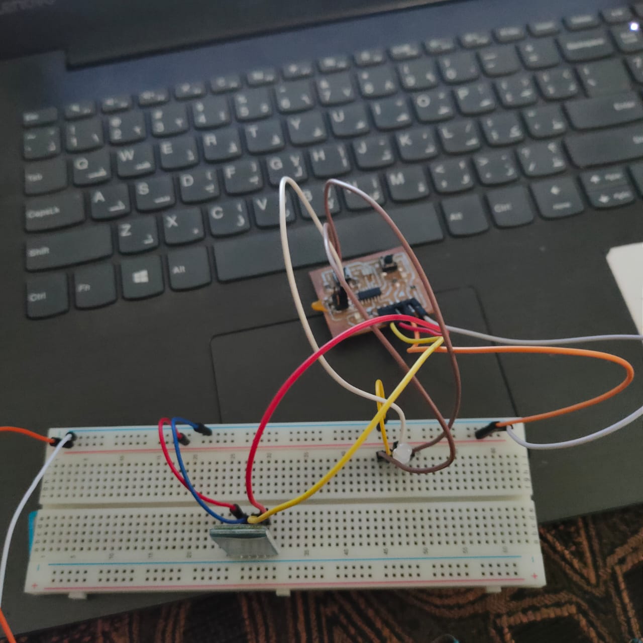
This week I used the board I made at Electronics Design Week
I did an experiment with the Bluetooth module HC- 05 and the LED and turned it on and off with an app bluetooth terminal
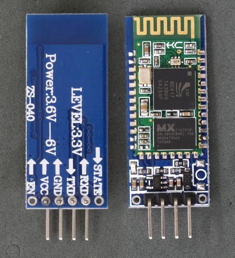
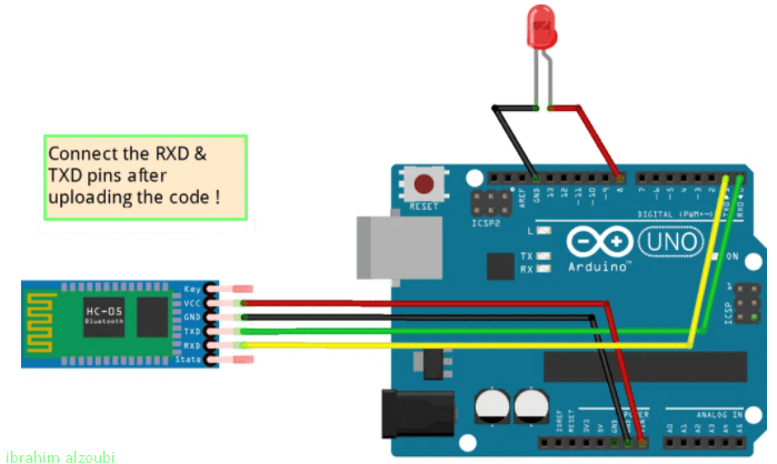
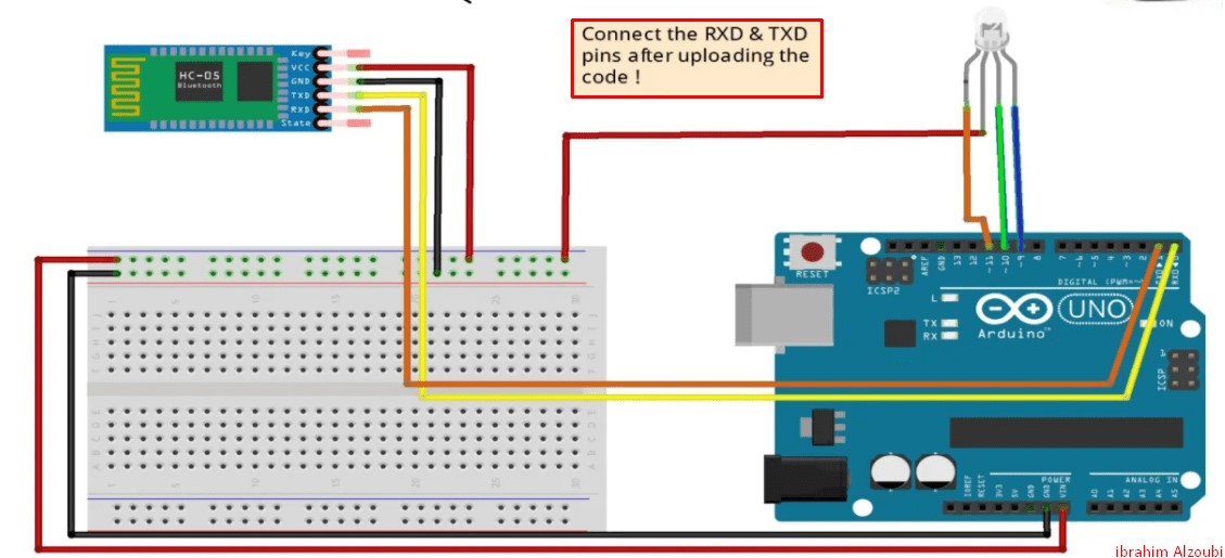
Connections Of Bluetooth module HC05 :
Things you’ll need
- your board
- Breadboard
- Bluetooth module/sensor – HC05
- Couple of jumpers/single stranded wires
- LEDs
VCC – to VCC of Arduino.
GND – to GND of Arduino.
RX – to digital pin 0(TX pin) of Arduino.
TX – to digital pin 1(RX pin) of Arduino. (connect RX & TX pin after uploading the code)
Of LED –
Positive terminal – to pin 8 of Arduino.
Negative terminal – GND of Arduino.
Code :)
    void setup() {

Serial.begin(9600);

 pinMode(8, OUTPUT); // put your setup code here, to run once:

 }


void loop() {

  // put your main code here, to run repeatedly:

 if(Serial.available()>0)

   {

      char data= Serial.read(); // reading the data received from the bluetooth module

      switch(data)

      {

        case 'a': digitalWrite(8, HIGH);break; // when a is pressed on the app on your smart phone

        case 'd': digitalWrite(8, LOW);break; // when d is pressed on the app on your smart phone

        default : break;

      }

      Serial.println(data);

   }

   delay(50);

}
Everything is explained in the video and how to work on the program and operation, This was the result as shown in the video below:
In the second experiment that I did, it was about controlling LED rgb via voice commands using an application that supports voice commands via BT Voice Control for Arduino
Requirements :)
- board
- Breadboard
- Jumpers/single stranded wires
- RGB led
- Bluetooth module HC-05
- Android
Connections Of Bluetooth module HC05 :-
- VCC – to VCC of Arduino.
- GND – to GND of Arduino.
- RX – to digital pin 0(TX pin) of Arduino.
- TX – to digital pin 1(RX pin) of Arduino. (connect RX & TX pin after uploading the code)
- Of LED
- Longest terminal (2) – VCC
- Terminal 1 – Pin 9
- Terminal 3 – Pin 10
- Terminal 4 – Pin 11
Code :)
    String voice;


#define GREEN 10

#define BLUE 11

#define RED 9


void setup()

{                                            // put your setup code here, to run once:

  Serial.begin(9600);

   pinMode(GREEN, OUTPUT);

  pinMode(BLUE, OUTPUT);

  pinMode(RED, OUTPUT);

   analogWrite(RED,255);

   analogWrite(GREEN,255);                    // Since LED must be off in the beginning

   analogWrite(BLUE,255);

}


  int redVal;

  int greenVal;

  int blueVal;


void loop() {


  while (Serial.available())   //Check if there is an available byte to read

  {

  delay(10);                   //Delay added to make thing stable

  char c = Serial.read();      //Conduct a serial read

  if (c == '#') {break;}       //Exit the loop when the # is detected after the word

  voice += c;                  //Shorthand for voice = voice + c

  }


  if (voice.length() > 0) {

    Serial.println(voice);

  //----------Control Multiple Pins/ LEDs----------//


       if(voice == "*red")//                                FOR RED COLOUR OF THE LED

     {

     analogWrite(RED,0);

     analogWrite(GREEN,255);

     analogWrite(BLUE,255);

     }

  else if(voice == "*green")//                              FOR GREEN COLOUR OF THE LED !

     {

    analogWrite(GREEN,0);

    analogWrite(RED,255);

    analogWrite(BLUE,255);

     }

  else if(voice == "*blue")//                                FOR BLUE COLOUR OF THE LED !

     {

    analogWrite(RED,255);

    analogWrite(BLUE,0);

    analogWrite(GREEN,255);

     }


  else if(voice == "*white")//                               FOR WHITE COLOUR OF THE LED !

     {

    analogWrite(RED,0);

    analogWrite(GREEN,0);

    analogWrite(BLUE,0);

     }

   else if(voice == "*good night")//                          FOR TURNING OFF LED !

     {

    analogWrite(RED,255);

    analogWrite(GREEN,255);

    analogWrite(BLUE,255);

     }


    else if(voice == "*chameleon") //                           FOR FADING/CHANGING COLOURS !

     {
     redVal = 255; // choose a value between 1 and 255 to change the color.

     blueVal = 0;

     greenVal = 0;

     for(int i = 0; i < 255; i += 1) // fades out of red and into full (i = 255) green

    {

    greenVal += 1;

    redVal -= 1;

    analogWrite(GREEN, 255 - greenVal);

    analogWrite(RED, 255 - redVal);

    delay(10);
  }


  redVal = 0;

  blueVal = 0;

  greenVal = 255;

  for(int i = 0; i < 255; i += 1)

  {

    blueVal += 1;

    greenVal -= 1;

    analogWrite(BLUE, 255 - blueVal);

    analogWrite(GREEN, 255 - greenVal);

    delay(10);

  }


  redVal = 0;

  blueVal = 255;

  greenVal = 0;

  for(int i = 0; i < 255; i += 1)

  {

    redVal += 1;

    blueVal -= 1;

    analogWrite(RED, 255 - redVal);

    analogWrite(BLUE, 255 - blueVal);

    delay(10);

  }

   }

voice="";
                                                    //Reset the variable after initiating
}

}
Everything is explained in the video and how to work on the program and operation, This was the result as shown in the video below
In this experiment I use SPI on the Arduino to communicate between two Arduino boards
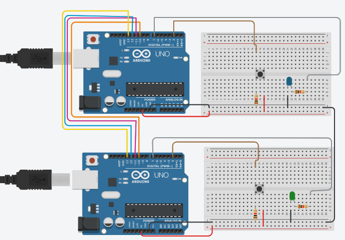
I will use SPI Protocol for communication between two Arduinos. where one Arduino will act as Master and another one will act as Slave, two LEDs and push buttons will be connected to both the arduinos. To demonstrate SPI communication, we will control master side LED by the push button at slave side and vice versa using the SPI Serial communication protocol.What is SPI?
SPI (Serial Peripheral Interface) is a serial communication protocol. SPI interface was found by Motorola in 1970. SPI has a full duplex connection, which means that the data is sent and received simultaneously. That is a master can send data to slave and a slave can send data to master simultaneously. SPI is synchronous serial communication means the clock is required for communication purpose. Below is the block diagram representation of SPI Master with Single Slave.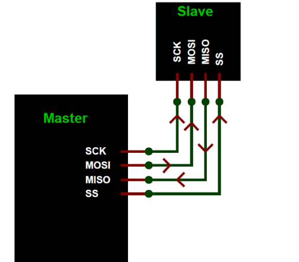
- MISO (Master in Slave Out) - The Slave line for sending data to the master.
- MOSI (Master Out Slave In) - The Master line for sending data to the peripherals.
- SCK (Serial Clock) - The clock pulses which synchronize data transmission generated by the master.
- SS (Slave Select) –Master can use this pin to enable and disable specific devices.
SPI has following four lines MISO, MOSI, SS, and CLK
- Arduino UNO (2)
- LED (2)
- Push Button (2)
- Breadboard
- Resistor 2.2k (2)
- Connecting Wires
- Resistor 10k (2)
Components I used in my experience
Arduino SPI Communication Circuit Diagram by using Tinkercad
Code Arduino
 Master Arduino Code:
//SPI MASTER (ARDUINO)
//SPI COMMUNICATION BETWEEN TWO ARDUINO
//CIRCUIT DIGEST

#include                             //Library for SPI
#define LED 7
#define ipbutton 2
int buttonvalue;
int x;
void setup (void)

{
  Serial.begin(115200);                   //Starts Serial Communication at Baud Rate 115200

  pinMode(ipbutton,INPUT);                //Sets pin 2 as input
  pinMode(LED,OUTPUT);                    //Sets pin 7 as Output

  SPI.begin();                            //Begins the SPI commnuication
  SPI.setClockDivider(SPI_CLOCK_DIV8);    //Sets clock for SPI communication at 8 (16/8=2Mhz)
  digitalWrite(SS,HIGH);                  // Setting SlaveSelect as HIGH (So master doesnt connnect with slave)
}

void loop(void)
{
  byte Mastersend,Mastereceive;

  buttonvalue = digitalRead(ipbutton);   //Reads the status of the pin 2

  if(buttonvalue == HIGH)                //Logic for Setting x value (To be sent to slave) depending upon input from pin 2
  {
    x = 1;
  }
  else
  {
    x = 0;
  }

  digitalWrite(SS, LOW);                  //Starts communication with Slave connected to master

  Mastersend = x;
  Mastereceive=SPI.transfer(Mastersend); //Send the mastersend value to slave also receives value from slave

  if(Mastereceive == 1)                   //Logic for setting the LED output depending upon value received from slave
  {
    digitalWrite(LED,HIGH);              //Sets pin 7 HIGH
    Serial.println("Master LED ON");
  }
  else
  {
   digitalWrite(LED,LOW);               //Sets pin 7 LOW
   Serial.println("Master LED OFF");
  }
  delay(1000);
}

Slave Arduino Code:
//SPI SLAVE (ARDUINO)
//SPI COMMUNICATION BETWEEN TWO ARDUINO
//CIRCUIT DIGEST
//Pramoth.T

#include
#define LEDpin 7
#define buttonpin 2
volatile boolean received;
volatile byte Slavereceived,Slavesend;
int buttonvalue;
int x;
void setup()

{
  Serial.begin(115200);

  pinMode(buttonpin,INPUT);               // Setting pin 2 as INPUT
  pinMode(LEDpin,OUTPUT);                 // Setting pin 7 as OUTPUT
  pinMode(MISO,OUTPUT);                   //Sets MISO as OUTPUT (Have to Send data to Master IN

  SPCR |= _BV(SPE);                       //Turn on SPI in Slave Mode
  received = false;

  SPI.attachInterrupt();                  //Interuupt ON is set for SPI commnucation

}

ISR (SPI_STC_vect)                        //Inerrrput routine function
{
  Slavereceived = SPDR;         // Value received from master if store in variable slavereceived
  received = true;                        //Sets received as True
}

void loop()
{ if(received)                            //Logic to SET LED ON OR OFF depending upon the value recerived from master
   {
      if (Slavereceived==1)
      {
        digitalWrite(LEDpin,HIGH);         //Sets pin 7 as HIGH LED ON
        Serial.println("Slave LED ON");
      }else
      {
        digitalWrite(LEDpin,LOW);          //Sets pin 7 as LOW LED OFF
        Serial.println("Slave LED OFF");
      }

      buttonvalue = digitalRead(buttonpin);  // Reads the status of the pin 2

      if (buttonvalue == HIGH)               //Logic to set the value of x to send to master
      {
        x=1;

      }else
      {
        x=0;
      }

  Slavesend=x;
  SPDR = Slavesend;                           //Sends the x value to master via SPDR
  delay(1000);
}
}
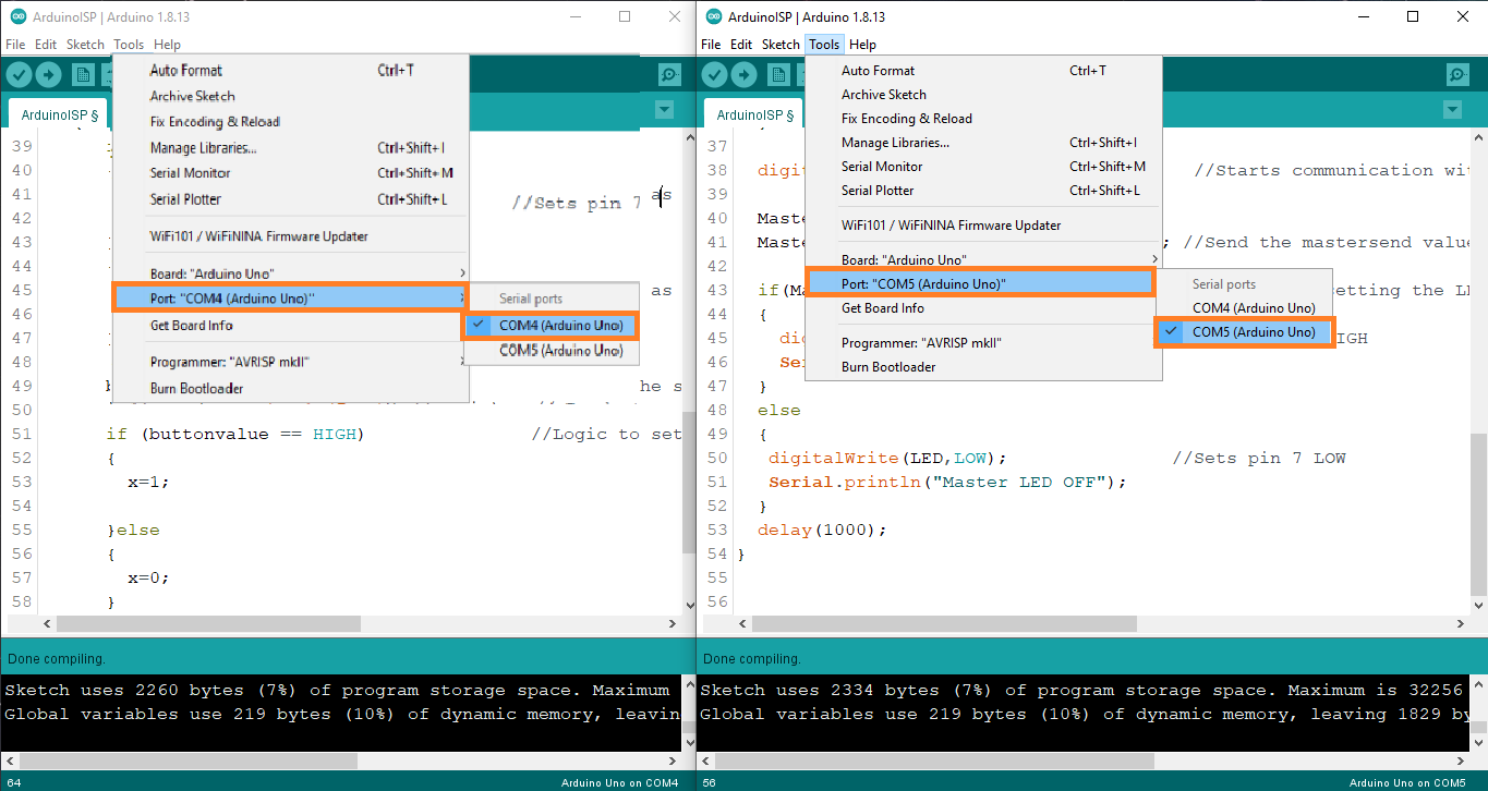
uploading the code separately for each Arduino, making sure the connected entries COM4 and COM5 are as shown in the picture